Category: PCB Layouts


Regulated Power Supply

regulated power supply schematic

This curcuit here is a regulated power supply. It’s made using linear regulators 7815 and 7915 for positive and negative voltages. It’s perfectly suitable for driving a preamplifier, tone corrections and anything else that runs on these voltages. It’s current limit  is 500mA because the regulators are without a heatsink, otherwise with a heatsink max current is 1.5A. You can swap the regulators for higher or lower voltages – they are interchangable.

regulated power supply overlay

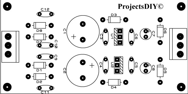
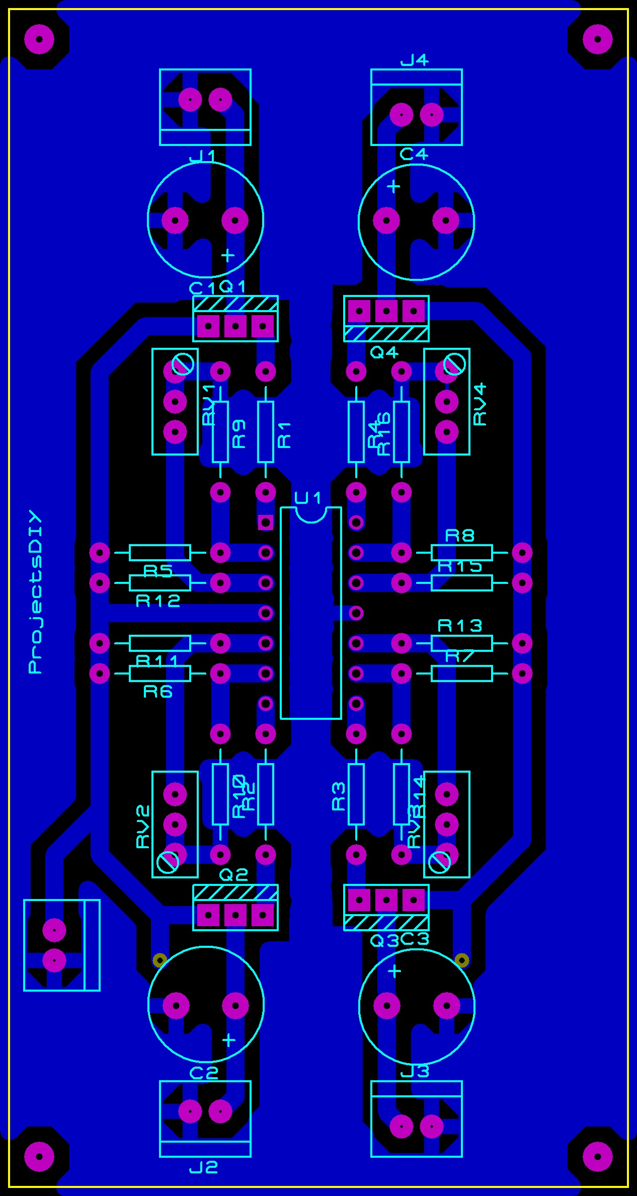
This is the top overlay layer. The dimensions are 42mmX83mm. The connectors can be a pcb block type or others with a distance of 3.96mm between pins. The regulators are in TO-220 package. All diodes are in DO-41 package and all ceramic capacitors are with 5mm distance between pins. The large electrolytic capacitors are with 7mm distance between pins and are 13mmX25mm in size. The small ones are 5mmX11mm in size.

Regulated Power Supply

Regulated Power Supply

LM317t 3D Preview

Image

LM317t PCB Layout

lm317

I know this is something that can be found in all electronics related sites and blogs ,but there is a reason.
Lm317 is probably the most used variable  voltage regulator and in one point everybody
will need a small and easy to make voltage regulator . Input voltage that can be as high as 32v ,
and the out put can go up to 25v . Drawn current can be up to 1.5 amps and 3A peak.
Component list :
C1 – 10 uF 25v rated
C2- 2200 uF 25v rated
D1 and D2 – 1N4007 ( all diodes from 1N4001- 1N4007 will work just fine)
R1 – 270R 1% tolerance should be used
Rv 1 – 4.7k Multi turn or ordinary potentiometer can be used .
Ic Lm317t
Br1 – should be atleast 100 v and 1 amp.
If you need and Output voltage that lm78XX series cant deliver use this one .


PCB layout for the 4 channel fan control

4 channel fan controlThis is the PCB i made for the 4 channel fan control.Hope you like it!
And here is the component list as promised :
R9, R10, R14 and R16 – are the temperature  sensing resistors(thermistors NTC) 10k
R5,R6,R7 and R8 – 10k
R11,R12,R13 and R15 – 10k
R1,R2,R3 and R4 – 1k
Rv1, RV2,RV3 and Rv4 – 10k mono type potentiometers
C1-C4 – 470uF atleast 16 v rated or more
Q1- Q4 – BD140 (can be replaced with other small PNP transistors )
Ic – TL064 (all TL0*4 series op amps work in this board)